Sound modeling
This article is devoted to the subject of loudspeakers. We will try to dispel many myths about them and explain what loudspeakers really are, both traditional ones and those with the possibility of acoustic beam modeling.
First, let’s introduce some basic electroacoustics definitions that we will operate on in this article. A loudspeaker is a single electro-acoustic transducer that is mounted in the housing. Only the combination of several loudspeakers in one housing creates a loudspeaker set. A special type of loudspeakers are loudspeakers.
What is a loudspeaker?
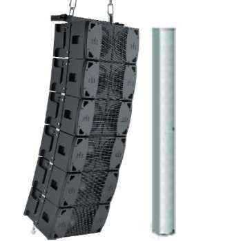
A loudspeaker is for many people any speaker placed in a housing, but it is not entirely true. A loudspeaker column is a specific loudspeaker device, which in its housing has several to a dozen or so of the same electro-acoustic transducers (speakers) arranged vertically. Thanks to this structure, it is possible to create a source with properties similar to a linear source, of course for a certain frequency range. The acoustic parameters of such a source are directly related to its height, the number of speakers placed in it and the distances between the transducers. We will try to explain the principle of operation of this specific device, as well as explain the principle of operation of the increasingly popular columns with digitally controlled acoustic beam.
What are sound modeling speakers?
The loudspeakers recently found on our market have the option of modeling the acoustic beam. The dimensions and appearance are very similar to traditional loudspeakers, well known and used since the XNUMXs. Digitally controlled loudspeakers are used in similar installations as their analog predecessors. This type of loudspeaker devices can be found, among others, in churches, passenger terminals at railway stations or airports, public spaces, courts and sports halls. However, there are many aspects where digitally controlled acoustic beam columns outweigh traditional solutions.
Acoustic aspects
All the above-mentioned places are characterized by relatively difficult acoustics, related to their cubature and the presence of highly reflective surfaces, which translates directly into the large reverberation time RT60s (RT60 “reverbation time”) in these rooms.
Such rooms require the use of loudspeaker devices with high directivity. The ratio of direct to reflected sound must be high enough for the intelligibility of speech and music to be as high as possible. If we use traditional loudspeakers with less directional characteristics in an acoustically difficult room, it may turn out that the generated sound will be reflected from many surfaces, so the ratio of direct sound to reflected sound will significantly decrease. In such a situation, only listeners who are very close to the sound source will be able to properly understand the message reaching them.

Architectural aspects
In order to obtain the appropriate ratio of the quality of the generated sound in relation to the price of the sound system, a small number of loudspeakers with a high Q factor (directivity) should be used. So why do we not find large tube systems or line-array systems in the aforementioned facilities, such as stations, terminals, churches? There is a very simple answer here – architects create these buildings largely guided by aesthetics. Large tube systems or line-array clusters do not match the architecture of the room with their size, which is why architects do not agree to their use. The compromise in this case was often the loudspeakers, even before special DSP circuits and the ability to control each of the drivers were invented for them. These devices can be easily hidden in the architecture of the room. They are usually mounted close to the wall and can be colored with the color of the surrounding surfaces. It is a much more attractive solution and, above all, more readily accepted by architects.
Line-arrays are not new!
The principle of the linear source with mathematical calculations and the description of their directivity characteristics was very well described by Hary F. Olson in his book “Acoustical Engineering”, published for the first time in 1940. There we will find a very detailed explanation of the physical phenomena occurring in loudspeakers using the properties of a line source
The following table shows the acoustic properties of traditional loudspeakers:

One disadvantageous property of loudspeakers is that the frequency response of such a system is not flat. Their design generates much more energy in the low frequency range. This energy is generally less directional, so the vertical dispersion will be much greater than for higher frequencies. As it is commonly known, acoustically difficult rooms are usually characterized by a long reverberation time in the range of very low frequencies, which, due to the increased energy in this frequency band, may result in a deterioration of speech intelligibility.
To explain why loudspeakers behave this way, we will briefly go over some basic physical concepts for traditional loudspeakers and those with digital acoustic beam control.
Point source interactions
• Directivity of two sources
When two point sources separated by half wavelength (λ / 2) generate the same signal, the signals below and above such an array will cancel each other out, and on the axis of the array the signal will be amplified twice (6 dB).

λ / 4 (one quarter of the wavelength – for one frequency)
When two sources are spaced apart by a length of λ / 4 or less (this length, of course, refers to one frequency), we notice a slight narrowing of the directional characteristics in the vertical plane.

λ / 4 (one quarter of the wavelength – for one frequency)
When two sources are spaced apart by a length of λ / 4 or less (this length, of course, refers to one frequency), we notice a slight narrowing of the directional characteristics in the vertical plane.

λ (one wavelength)
A difference of one wavelength will amplify the signals both vertically and horizontally. The acoustic beam will take the form of two leaves

2l
As the ratio of the wavelength to the distance between the transducers increases, the number of side lobes also increases. For a constant number and distance between transducers in linear systems, this ratio increases with frequency (this is where waveguides come in handy, very often used in line-array sets).

Limitations of line sources
The distance between the individual speakers determines the maximum frequency for which the system will act as a line source. The source height determines the minimum frequency for which this system is directional.

Source height versus wavelength
λ / 2
For wavelengths greater than twice the height of the source, there is hardly any control of the directional characteristics. In this case, the source can be treated as a point source with a very high output level.

λ
The height of the line source determines the wavelength for which we will observe a significant increase in directivity in the vertical plane.

2 l
At higher frequencies, the beam height decreases. Side lobes start to appear, but compared to the energy of the main lobe, they have no significant effect.

4 l
The vertical directionality increases more and more, the main lobe energy continues to increase.

Distance between individual transducers versus wavelength
λ / 2
When the transducers are no more than half the wavelength apart, the source creates a very directional beam with minimal side lobes.

λ
Side lobes with significant and measurable energy are formed with increasing frequency. This doesn’t have to be a problem as most of the listeners are outside of this area.

2l
The number of side lobes doubles. It is extremely difficult to isolate the listeners and reflective surfaces from this radiation area.
4l
When the distance between the transducers is four times the wavelength, so many side lobes are produced that the source starts to look like a point source and the directivity drops significantly.

Multi-channel DSP circuits can control the height of the source
The upper frequency range control depends on the distance between the individual high-frequency transducers. The challenge for designers is to minimize this distance while maintaining the optimal frequency response and the maximum acoustic power generated by such a device. Line sources become more and more directional as the frequency increases. At the highest frequencies, they are even too directional to consciously use this effect. Thanks to the possibility of using separate DSP systems and amplification for each of the transducers, it is possible to control the width of the generated vertical acoustic beam. The technique is simple: just use low-pass filters to reduce levels and the usable frequency range for the individual loudspeakers in the cabinet. To move the beam away from the center of the housing, we change the filter row and the cut-off frequency (the most gentle for the speakers located in the center of the housing). This type of operation would be impossible without the use of a separate amplifier and DSP circuit for each loudspeaker in such a line.

A traditional loudspeaker allows you to control a vertical acoustic beam, but the width of the beam changes with frequency. Generally speaking, the directivity factor Q is variable and lower than required.
Acoustic beam tilt control
As we well know, history likes to repeat itself. Below is a chart from the book by Harry F. Olson “Acoustical Engineering”. Digitally delaying the radiation of the individual speakers of a line source is exactly the same as physically sloping the line source. After 1957, it took a long time for technology to make use of this phenomenon, while keeping costs at an optimal level.
Line sources with DSP circuits solve many architectural and acoustic problems
• Variable vertical directivity factor Q of the radiated acoustic beam.
DSP circuits for line sources make it possible to change the width of the acoustic beam. This is possible thanks to the interference check for individual speakers. The ICONYX column from the American company Renkus-Heinz allows you to change the width of such a beam in the range: 5, 10, 15 and 20 °, of course, if such a column is sufficiently tall (only the IC24 housing allows you to select a beam with a width of 5 °). In this way, a narrow acoustic beam avoids unnecessary reflections from the floor or ceiling in highly reverberant rooms.
Constant directivity factor Q with increasing frequency
Thanks to DSP circuits and power amplifiers for each of the transducers, we can maintain a constant directivity factor over a wide frequency range. It not only minimizes the reflected sound levels in the room, but also a constant gain for a wide frequency band.
Possibility to direct the acoustic beam regardless of the place of installation
Although control of the acoustic beam is simple from a signal processing point of view, it is very important for architectural reasons. Such possibilities lead to the fact that without the necessity to tilt the loudspeaker physically, we create an eye-friendly sound source that blends with the architecture. ICONYX also has the ability to set the location of the acoustic beam center.
The use of modeled linear sources
• Churches
Many churches have similar features: very high ceilings, stone or glass reflective surfaces, no absorbing surfaces. All this causes that the reverberation time in these rooms is very long, reaching even a few seconds, which makes the speech intelligibility very poor.
• Public transport facilities
Airports and railway stations are very often finished with materials with similar acoustic properties to those used in churches. Public transport facilities are important because messages about arrivals, departures or delays reaching passengers must be understandable.
• Museums, Auditoriums, Lobby
Many buildings of a smaller scale than public transport or churches have similar unfavorable acoustic parameters. The two main challenges for digitally modeled line sources are the long reverberation time which adversely affects speech intelligibility, and the visual aspects, which are so important in the final selection of the type of public address system.
Design criteria. Full-band acoustic power
Each line source, even those with advanced DSP circuits, can only be controlled within a certain useful frequency range. However, the use of coaxial transducers forming a line source circuit provides full-range acoustic power over a very wide range. The sound is therefore clear and very natural. In typical applications for speech signals or full-range music, most of the energy is in the range that we can control thanks to the built-in coaxial drivers.
Full control with advanced tools
To maximize the efficiency of a digitally modeled linear source, it is not enough to use only high-quality transducers. After all, we know that in order to have full control over the parameters of the loudspeaker, we must use advanced electronics. Such assumptions forced the use of multi-channel amplification and DSP circuits. The D2 chip, used in the ICONYX loudspeakers, provides full-range multi-channel amplification, full control of DSP processors and optionally several analog and digital inputs. When the encoded PCM signal is delivered to the column in the form of AES3 or CobraNet digital signals, the D2 chip immediately converts it into a PWM signal. First generation digital amplifiers converted the PCM signal first into analog signals and then into PWM signals. This A / D – D / A conversion unfortunately increased cost, distortion and latency considerably.
Flexibility
The natural and clear sound of digitally modeled line sources makes it possible to use this solution not only in public transport facilities, churches and museums. The modular structure of ICONYX columns allows you to assemble line sources according to the needs of a given room. Control of each element of such a source gives great flexibility when setting, for example, many points, where the acoustic center of the radiated beam is created, i.e. many line sources. The center of such a beam can be located anywhere along the entire height of the column. It is possible due to keeping small constant distances between high-frequency transducers.
The horizontal radiation angles depend on the column elements
As with other vertical line sources, the sound from the ICONYX can only be controlled vertically. The horizontal beam angle is constant and depends on the type of transducers used. Those used in the IC column have a beam angle in a wide frequency band, the differences are in the range of 140 to 150 Hz for sound in the band from 100 Hz to 16 kHz.


The wide angle of radiation gives greater efficiency
The wide dispersion, especially at high frequencies, ensures better coherence and intelligibility of the sound, especially at the edges of the directivity characteristic. In many situations, a wider beam angle means that fewer loudspeakers are used, which translates directly into savings.
The actual interactions of the pickups
We know very well that the directivity characteristics of a real speaker cannot be uniform across the entire frequency range. Due to the size of such a source, it will become more directional as the frequency increases. In the case of ICONYX loudspeakers, the speakers used in it are omni-directional in the band up to 300 Hz, semicircular in the range from 300 Hz to 1 kHz, and for the band from 1 kHz to 10 kHz, the directivity characteristic is conical and its beam angles are 140 ° × 140 °. The ideal mathematical model of a linear source composed of ideal omnidirectional point sources will therefore differ from the actual transducers. The measurements show that the backward radiation energy of the real system is much smaller than the mathematically modeled one.
ICONYX @ λ (wavelength) line source


We can see that the beams have a similar shape, but for the IC32 column, four times larger than IC8, the characteristic narrows significantly.

For the frequency of 1,25 kHz, a beam is created with a radiation angle of 10 °. The side lobes are 9 dB less.

For the frequency of 3,1 kHz we see a well focused acoustic beam with an angle of 10 °. By the way, two side lobes are formed, which are significantly deviated from the main beam, this does not cause negative effects.
Constant directivity of ICONYX columns

For the frequency of 500 Hz (5 λ), the directivity is constant at 10 °, which was confirmed by previous simulations for 100 Hz and 1,25 kHz.
Beam tilt is a simple progressive retardation of successive loudspeakers
If we physically tilt the loudspeaker, we shift the subsequent drivers in time relative to the listening position. This type of shift causes the “sound slope” towards the listener. We can achieve the same effect by hanging the speaker vertically and introducing increasing delays for the drivers in the direction in which we want to direct the sound. For effective steering (tilting) of the acoustic beam, the source must have a height equal to twice the wavelength for the given frequency.

With the modular structure of ICONYX columns, it is possible to effectively tilt the beam for:
• IC8: 800Hz
• IC16: 400Hz
• IC24: 250Hz
• IC32: 200Hz
BeamWare – ICONYX Column Beam Modeling software
The modeling method described earlier shows us what type of action on the digital signal we need to apply (variable low-pass filters on each loudspeaker in the column) to get the expected results.
The idea is relatively simple – in the case of the IC16 column, the software has to convert and then implement sixteen FIR filter settings and sixteen independent delay settings. In order to transfer the acoustic center of the radiated beam, using the constant distance between the high-frequency transducers in the column housing, we need to calculate and implement a new set of settings for all filters and delays.

Creating a theoretical model is necessary, but we must take into account the fact that the speakers actually behave differently, more directionally, and the measurements prove that the results obtained are better than those simulated with mathematical algorithms.
Nowadays, with such a great technological development, computer processors are already equal to the task. BeamWare uses a graphical representation of the results of the results by graphically entering information about the size of the listening area, height and location of the columns. BeamWare easily allows you to export the settings to the professional acoustic software EASE and directly save the settings to the column DSP circuits. The result of working in the BeamWare software is predictable, precise and repeatable results in real acoustic conditions.
ICONYX – a new generation of sound
• Sound quality
The sound of the ICONYX is a standard developed long ago by the producer Renkus-Heinz. The ICONYX column is designed to reproduce both speech signals and full-range music at the best.
• Wide dispersion
It is possible thanks to the use of coaxial speakers with a very wide angle of radiation (even up to 150 ° in the vertical plane), especially for the highest frequency range. This means a more consistent frequency response across the entire area and wider coverage, which means using fewer such loudspeakers in the facility.
• Flexibility
The ICONYX is a vertical loudspeaker with identical coaxial drivers placed very close to each other. Due to the small and constant distances between the loudspeakers in the housing, the displacement of the acoustic center of the radiated beam in the vertical plane is practically arbitrary. These types of properties are very useful, especially when the architectural constraints do not allow the proper location (height) of the columns in the object. The margin for the height of the suspension of such a column is very large. The modular design and full configurability allow you to define several line sources with one long column at your disposal. Each radiated beam can have a different width and different slope.
• Lower costs
Once again, thanks to the use of coaxial speakers, each ICONYX speaker allows you to cover a very wide area. We know that the height of the column depends on how many IC8 modules we connect to each other. Such a modular structure enables easy and cheap transport.
The main advantages of ICONYX columns
• More effective control of the vertical radiation of the source.
The size of the loudspeaker is much smaller than the older designs, while maintaining better directivity, which translates directly into intelligibility in reverberation conditions. The modular structure also allows the column to be configured according to the needs of the facility and financial conditions.
• Full-range audio reproduction
Previous loudspeaker designs had produced little satisfactory results with respect to the frequency response of such loudspeakers, as the useful processing bandwidth was in the range of 200 Hz to 4 kHz. ICONYX loudspeakers are a construction enabling the generation of full-range sound in the range from 120 Hz to 16 kHz, while maintaining a constant angle of radiation in the horizontal plane throughout this range. In addition, ICONYX modules are electronically and acoustically more efficient: they are at least 3-4 dB “louder” than their predecessors of similar size.
• Advanced electronics
Each of the converters in the housing is driven by a separate amplifier circuit and DSP circuit. When AES3 (AES / EBU) or CobraNet inputs are used, the signals are “digitally clear”. This means that DSP circuits directly convert PCM input signals to PWM signals without unnecessary A / D and C / A conversion.
• Advanced DSP circuits
The advanced signal processing algorithms developed especially for ICONYX columns and the eye-friendly BeamWare interface facilitate the work of the user, thanks to which they can be used in a wide range of their possibilities in many facilities.
Summation
This article is devoted to a detailed analysis of loudspeakers and sound modeling with advanced DSP circuits. It is worth emphasizing that the theory of physical phenomena that use both traditional and digitally modeled loudspeakers was described already in the 50s. Only with the use of much cheaper and better electronic components is it possible to fully control the physical processes in the processing of acoustic signals. This knowledge is generally available, but we still meet and we will meet cases where misunderstanding of physical phenomena leads to frequent errors in the arrangement and location of loudspeakers, an example may be the often horizontal assembly of loudspeakers (for aesthetic reasons).
Of course, this type of action is also used consciously, and an interesting example of this is the horizontal installation of columns with speakers pointing downwards on the platforms of railway stations. By using the loudspeakers in this way, we can get closer to the “shower” effect, where, going beyond the range of such a loudspeaker (the dispersion area is the housing of the column), the sound level drops significantly. In this way, the reflected sound level can be minimized, achieving a significant improvement in speech intelligibility.
In those times of highly developed electronics, we meet more and more often innovative solutions, which, however, use the same physics that was discovered and described a long time ago. Digitally modeled sound gives us amazing possibilities to adapt to acoustically difficult rooms.
The producers are already announcing a breakthrough in sound control and management, one of such accents is the appearance of completely new loudspeakers (modular IC2 by Renkus-Heinz), which can be put together in any way to obtain a high-quality sound source, fully managed while being a linear source and point.